160+80+40 on One inverted L. To add the 40m third band to the dual-band project, see . Particulars of a one year evaluation are now included in the article.
Without any change to the aerial wire, there is a way to use an already installed and working 160 meters Inverted L over FCP with Isolation Transformer (160 L/IsoT/FCP) as an excellent 80 meter end-fed halfwave L (80EFHWL).
We are not tacking on a compromise antenna just so we can say it covers 80 meters. Rather we enhance near-the-ground components of an existing efficient 160 inverted L to add an efficient omnidirectional 80m operation. Then a multiband solution for higher bands can use shorter 40m ½ λ wires without the need for longer 80m ½ λ wires.
The 80m EFHWL is a single wire antenna without the pattern null points of a vertical, dipole or inverted vee. The EFHWL has an essentially omnidirectional, roughly hemispherical 3D pattern that works well for both local and DX.
From 2011 until his passing, W0UCE worked 80m by feeding his 160m L/FCP as an 80EFHWL, using an early equivalent to the circuit below. The 80EFHWL was always his best performing antenna on 80m.
For local coverage, the 80EFHWL lacks the skip zone weaknesses of the vertical, having no doughnut hole in the high angle pattern. The horizontal wire fills in the doughnut hole without taking power from the EFHWL low angle pattern. The EFHWL has reduced RF ground fields in front of the L reducing ground loss versus a ¼ λ vertical. This supplies recovered loss to fill in the doughnut hole.
For DX, the 80EFHWL has a better vertical polarization component than a ¼ λ vertical with near or in-ground radials/counterpoise. A ¼ λ vertical has it's highest RF current down at the bottom of the vertical radiator where nearness to ground subjects it to maximum ground induction loss.
In contrast the 80EFHWL has its lowest RF current near the ground. It has its highest RF current at the top around the bend. This improves efficiency by keeping the bulk of RF current well away from ground and its radiation not obstructed by ground clutter and trees to low DX takeoff angles.
For DX, an 80EFHWL will defeat an 80m dipole or inverted V with supports in the 50-60-70 foot (15-20m) neighborhood. An 80m dipole or V needs at least ½ λ elevation, the 130 foot (40m) neighborhood, for it's best low angle DX.
Correctly done, the 80EFHWL is a proven strong performer. Some argue that the EFHWL is the best all-around single wire antenna for 80m.
The aspect of a low-band EFHWL keeping its performance from making it wildly popular has always been the need for a remote tuning device at the base of the halfwave wire. With a feed Z sometimes more than 2000 ohms, the EFHWL cannot directly match 50 ohm coax. It has no commercial off-the-shelf remote tuning product designed for it.
The existing 160L/IsoT/FCP feed configuration has already established the point of opportunity for 80 meter adaptation, with at least an IsoT. A relay at the center of the FCP easily flips the FCP to an effective and efficient counterpoise for 80m.
If you do not already have an existing 160 meter L/IsoT/FCP, you begin the 160/80 project by putting up a 160 meter L/IsoT/FCP and making all adjustments to get 160 working well. You do not tune the 80 meter matching circuitry until 160 operation is satisfactory.
The 80 meter tuning circuitry is switched out of line during 160 operation. Adding or changing the 80 meter operation will not materially affect 160m. Changing the aerial wire, the FCP, or the isolation transformer for the 160 meter operation will detune 80 meters.
For 80 meters:
1) The 160 meter L aerial wire is used as is, no changes. No traps or coils or double wires are needed in the aerial wire.
2) The 160 meter isolation transformer is used as is, no changes.
3) the 160 meter FCP has one item added, otherwise physically unchanged: A knife switch or high voltage relay is added shorting between the FCP feed point and the middle of the third wire to "flip" the FCP to 80M operation. See the red connection in the following diagram:
With the red wire connection open (not shorted), the FCP is on 160 meters. Closed (shorted), it's on 80 meters. The relay and shorting wire's physical layout needs to be brief. Otherwise they will detune the FCP's 160 operation and increase loss by undoing the net zero sum of fields. To avoid this:
3a) Keep the distance between the center of the FCP's third folded wire and the relay points or switch as short as possible.
3b) After 3a), keep the connection from the relay to the FCP feed as direct as possible. The relay or switch will need to be up on the FCP center support.
At K2AV this means the relay is mounted in the usual 4x4 sealable plastic electrical box affixed to the center spreader.
3c) At a site where the works are contained in a project box at the center of the FCP, 3a), 3b) requirements bear on wiring layout inside the box. When picking wire and insulation and routing these wires, remember the up to 12kV p-p RF running around. For these RF connections do not use wire with unknown insulation characteristics. Some lengths of wire/sleeving left over from trimming the isolation transformer leads may be a good choice. Or use #14 AWG (2.5 mmsq) bare solid copper wire in standard wall #12 PTFE tubing.
The shorting connection points are an RF high voltage point when open. The modeled RF voltage for 160 meter 1500 watt operation at the switching point is up to 12 kV peak to peak, requiring attention to a shorting relay or switch able to tolerate a 12 kV DC operating voltage or better. Satisfying this need is discussed below in "Band and Band Range Switching Relays".
4) For 80 meters, a DPDT knife switch or DPDT relay switches in a tapped parallel LC tuning network to tune the now high feed impedance of the unchanged aerial wire.
5) A later addition will extend this scheme to two ranges in 1.8-2 MHz and up to five ranges in 3.5-4 MHz. Each desired range on 80 will require a separate additional DPDT relay and pair of taps. This will require a switch box in the shack and multi-conductor cable to the switch.
Here is the diagram for a single tuned range on 160 and a single tuned range on 80. For those who only operate CW on 160 and 80, this simple circuit may be enough.
A single, separate twisted pair of wires should transport the relay energizing voltage for this single range per band setup. This wire pair will need a common mode choke at the tuning network to be prevent the wire pair becoming a source of noise to the antenna and a ground shunt to the antenna system.
There should be a second choke on the wire pair between the tuning network and the station entry ground, either just on the antenna side of the station entry ground or approximately 65 feet (20m) from the tuning network, whichever is closest to the tuning network. Place a common mode choke on the feed coax at this same point.
It is clear from field experience there are no one-size-fits-all values for the coil and capacitor. You may have to experiment with values. Our original and work-most-of-the-time starting values are below.
Please advise us of changes in supply and/or new sources of supply for identical or equivalent material.
We currently estimate a fixed 500 ρF high voltage, high current (fully derated 5 kV, rated 10 amps RF at 3.5 MHz) transmitting doorknob or vacuum capacitor. It is easy enough to find fixed caps with the voltage rating. But other parameters are just as important.
The RF current rating at frequency must be known and is not always available. Do not use capacitors without a known, adequate current rating. Other than being destroyed by heat from I²×R loss, capacity change with heat will cause the tuning to wander. Unfortunately, the physical size of a doorknob cap does not guarantee its current carrying ability.
500 ρF, with adequate voltage and amperage ratings, can be provided in a number of ways.
♦ Vacuum capacitors are the most stable, generally with high voltage and current ratings, if one owns or wishes to procure them.
♦ Russian surplus transmitting doorknob caps are available that show a kVA reactive rating. Some of these Russian caps appear heavy duty, but we have scattered, verified reports of destroying "large" Russian caps with 1500 watts in this application.
Russian KVA lettering looks like kBAp or KBAP. Caps with these labels usually include a kB rating which is kV. Divide the kBAp by kB which will give you its most conservative maximum current rating. One such 470 ρF cap has 15kB and 40kBAp or 2.7 amps. That might be OK, depending on its dielectric material and physical surface area. It can certainly be tried, but without frequency derating curves can't be confidently engineered, and therefore gets no unqualified recommendation. You will know a particular cap is not going to make it if under full power the SWR starts to drift, indicating heat-induced change to the capacitor value.
See the HEC documentation below for an example of derating curves.
♦ Probably the least price, fully rated, made from currently produced, stock store-bought components, a 500 ρF transmitting capacitor can be made with three paralleled High Energy Corp (HEC) HT50 "barrel" style ceramic transmitting caps. Three 7.5 kV 170 ρF (HT50V171KA) in parallel will produce 510 ρF.
HEC HT50 transmitting caps actually manufactured by HEC are fully specified with derating curves on HEC's web site. See pp 10, 11 of the document. Three 7.5 kV 170 ρF in parallel will be rated 30 kVA, with a 3.5 MHz derated current of 5 amps each for a robust total 15 amps at 7.5 kV. See page 11 rating curve graph HT50V101KA, which applies to the 170 ρF's N750 material.
Three 170 ρF in parallel was deliberately chosen over a single HEC HT50 500 ρF for a number of reasons:
At this writing these 170 ρF caps, apparently three different brands including HEC, are available from Surplus Sales of Nebraska as their part (CFC)HT580170-75 , Look down the page under HT-50/58 Series. MFJ sells them as their 290-0170-7, two used as load capacitor padding on 160 in their AL-82, AL-1200 and AL-1500 QRO amps. You will have to order them verbally via Ameritron technical support, they (and most of their parts now) are no longer listed in their catalog or web site. RF Parts sells them as their 580170-7 . See links or inquire for prices. At this writing, the RF Parts illustration shows the HEC branding on the capacitor. So we have a source for the documented brand, with comparable price.
As of (V.2019.03.15), the bargain-priced JCSL-500-5S fixed value vacuum cap previously mentioned here is no longer for sale at MaxGain. From time to time such items will appear on Ebay or the sources above with limited quantities. The only way to find these bargains is to keep a lookout.
We estimate a large enough coil (3 µH) at 10 to 12 turns of solid bare #10 AWG copper wire, 3 inch (75 mm) diameter. Larger wire or copper tube wound on a 3 inch form may need more turns to achieve 3 µH. This can be any sufficiently rigid high current coil format providing enough turns and space between windings to allow placing and soldering taps to vary µH and ratios for tuning. To reduce loss the winding form should be removed from the coil for actual operation. Support the coil at each end. However, do not remove the four polystyrene bars that support manufactured coil stock. 3/16 or 1/4 inch copper tubing hand wound on a 3 inch form and mounted without the form to insulators at the ends may be the least expensive and most efficient winding.
Unfortunately, Ameritron (MFJ) has largely ceased operation, the complete story and status found elsewhere. For use in their AL82, AL1200, AL1500 full QRO amplifiers, Ameritron manufactured their own coils (#404-0024) for the pi-networks, a hefty, affordable 3 inch diameter, 4 TPI, #10 AWG stock, illustration left. A recent inquiry to purchase Ameritron's coil stock indicated that no stock remained and none would be manufactured. We are pursuing possibilities from ham cottage industry sources. If any pan out, they will be listed here.
For those who have Ameritron coil stock on hand and want to "harden it" and cut it to size before using it, see instructions here.
The 80/160 and 40/80/160 multi-banding L/FCP projects can use a three inch length of Ameritron coil stock (3 inch diameter, 4 turns per inch, #10 AWG). Once treated per (A) it has a near infinite shelf life. To keep from ruining coil stock during cutting, bending and installation, very easy to do, important information points apply. Please read A, B and C below:
(A) The coil stock itself is a bit fragile as manufactured. For this strengthening task only use Krazy Glue™ or an exact equivalent very thin consistency cyanoacrylate glue. Put a tiny drop of glue on both sides of the wire at all points where the wire is melted into the support rods. The very thin glue will soak into the tiny air bubble spaces where the wire embeds the plastic. Do not use a "regular" or "thick" glue. It will not soak into the bubble spaces.
Start on an 11 inch coil with a brand-new, unopened small bottle of Krazy Glue. You will use most of the bottle placing 178 drops for the 11 inches. Previously opened Krazy Glue does not store well, suffering loss of ingredients to the air with air pressure changes, even with a tightly closed cap. When you have finished the coil, unless you have something immediate to do with the rest of the glue, throw away the bottle.
Allow the full 24 hours for full curing before handling or cutting the coil into smaller pieces. When you have done this, the coil will have a distinct rigid solid "feel" to it.
(B) It is highly recommended that you cut the coil wire and plastic support rods with a Dremel tool or equivalent. Wire cutters create a large longitudinal pressure on the wire or plastic support rods during the cutting which can shatter the plastic or break the wire-plastic bond. Cutters work by pushing into the wire with a wedge-shaped cutting edge which tries to push the wire apart while the coil structure is trying to hold the wire together. A Dremel cuts by removing material.
When you are cutting a piece of the coil stock to use, leave extra length for forming mounting wires. To do this, leave an extra entire ¼ turn for connection on either end. Do not attempt to use the short ⅛ turn piece for connection. For three inches count 12 full turns plus two additional full ¼ turn sections, a total of 50 ¼ turn sections. In the middle of the 51st ¼ turn section cut the wire with the Dremel tool. Keep the angle of the cutting disk to the wire very small, almost parallel to the wire, to keep from scoring the adjacent turns. You can clean up the coil after you separate the 12 turn section.
Cut the wire before you cut the clear support rods. Otherwise you risk separating the wire from the support rods, which you will find amazingly difficult to repair.
Before cutting the support rods, twice carefully recount the ¼ turns, and twice carefully verify the cutting points. Mark the verified cutting points with a sharp tipped marker. It is very easy to get the cutting points mixed up if they are not marked.
Once the coil section has been separated, free the outside ends of the ¼ turn end wires from the support rods, cutting with the Dremel tool right next to the outer wire. You can then clean up the outer end of the ¼ turn worth of end wire with the Dremel tool.
Important: When forming the bends for the connecting ends of the coil, do not use the clear support rods as the rigid clamp for bending the wire. Use an end tip of a bench vise or vise-grip pliers to solidly grab the ¼ turn end wire right next to the clear support rod. Then make your bends, cuts, etc, with the vise protecting the fragile wire/support rod junction from any twisting or bending moment. Later on, if adjusting the mounting leads, always protect the wire/support rod junction.
(C) Until you have performed (A) on the coil stock, do not store or use this coil stock anywhere the air can be damp (including outdoors in an enclosure). Where the wire melts into the support rods, if the tiny bubbles get filled with water, carbon arc paths can develop under high power. The Krazy Glue fills the pockets where the tiny bubbles touch the wire. For that reason it is a good idea to do (A) when you first get the coil stock.
Vpp - Volts RF peak-to-peak, for antenna relay ciruitry design same as volts DC
VDC - Volts DC , for antenna relay circuitry design same as volts RF peak-to-peak
VRF - Volts RF, RMS Radio frequency voltage.
Vtb - Tested to this breakdown voltage, higher not guaranteed, may arc.
Vop - normal operating Vpp, keep circuit operating voltages at or below Vop to maintain safety factor.
If Vop not known, best use 80% Vtb as Vop, use remaining 20% up to Vtb as safety factor.
nnkVxx - following a number, kilovolts
NO - In SPST or DPST relays, contacts are normally open, current in winding closes contacts.
NC - In SPST or DPST relays, contacts are normally closed, current in winding opens contacts.
For long life, non-sealed relays should not be installed in non-desert outdoor or damp indoor locations. Especially avoid non-sealed relays if a location is excessively damp, near a body of salt water, or "monsoon season" is on your calendar. A 12kVop or better vacuum relay for the high kV FCP shorting relay, and three RJ1A or equivalent vacuum relays for the low kV matching circuit switching are the brute force, all situations QRO answer.
RJ1A and equivalents have a deserved reputation for early failure switching amplifiers QSK in CW contests. But in low kV L/FCP feedpoint matching, relays only change state with operator band changes. They should last indefinitely absent direct lightning strikes or band changes while key down QRO.
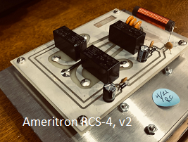
A lower cost possibility for mandatory sealed low kV applications is the Potter & Brumfield/Tyco/TE Connectivity RTE24012F DPDT sealed relay. It has been used over a decade by Ameritron in their RCS-4 control-over-coax remote coax switch. At this writing, the relay is very inexpensive with many sources. Google RTE24012F relay . The RTE24012F has a pair of 8A double throw contacts which can be paralleled for SPDT operation at 16A.
Of particular interest, the data sheet shows "Initial dielectric strength between open contacts = 1000Vrms. Or 1kVRF × 2.828 ≈ 2.8kVtb. 20% safety factor gives 2.2kVop.
See data sheet accented for RTE24012F for complete details. Click with magnifying glass if display is tall and narrow. Use back button to return here.
In the data sheet, RTE24012F is marked suitable for post-installation "washing", perhaps adding to the Ameritron choice. Note that the RTE24024F is a 24 volt otherwise identical version. Caution: Some relays that come up in a RTE24012F eBay search are not RTE24012F in the item's text. Expand the listing's photograph and be sure the markings on the relay case are Potter & Brumfield or Tyco or TE Connectivity and "RTE24012F". That way if you get something different, you have justification to return them for a refund due to "not as represented".
We note that post-pandemic, eBay listings of DPDT vacuum relays became rare and expensive. Prices for vacuum relays at Surplus Sales and MaxGain also increased. The non-vacuum, single relay to do the entire low kV switching, was the 12 volt DPDT Deltrol 20852-81, 24 volt 20852-82. We now only specify the Deltrol for dry or indoor locations as it is not sealed. It also doubled in price, with some Asia/Europe reports of difficulty in procurement.
These are listed at RS Americas, previously Allied Electronics . They are no longer listed at Array Solutions.
These Deltrol relays need to be protected from dampness in a sealed (not watertight or waterproof) enclosure. See the first four bullet points at Balun Design's Installation Notes PDF for useful time-tested advice for conditioning an enclosure for outdoors or damp locations. Even sealed relays will not work well if the connections are submerged in accumulated condensation.
For FCP shorting relay requirements, we ran EZNEC Pro on an L over FCP with a "load" in the FCP shorting wire to model voltage across open relay contacts. We used 100W, 200W, 500W, 1500W feeds and various L wire lengths and heights. RMS calculations showed 1kVRF, 1.5kVRF, 2.4kVRF 4.2kVRF, respectively, across the open contacts.
To calculate the operating DC or peak-to-peak voltage tolerances needed in relay specifications, we convert kVRF to RF peak-to-peak. Vop = Vpp = VRF × 2.828 . This generates 2.8kVop, 4.2kVop, 6.8kVop, 12kVop.
For a 20% safety factor we need DC breakdown tests at least 3.5kVtb, 5.3kVtb, 8.5kVtb, 15kVtb
K2AV uses a vacuum Jennings RD5A as FCP shorting relay for 40m & 80m operation on his 160m L/FCP. His RD5A is rated 12kVop, 15kVtb, operating faultless since 2013.
Modifications to the Deltrol DPDT relay can produce an SPST normally open shorting relay with .160 inch (4 mm) of total contact gap space. Both Normally Closed contacts are bent outward to increase the gap between the armature leaf contact and the Normally Open contact. The new gap is 80 mils (2 mm). The connection between the armature leaf and the base connection pin is removed on both poles. The two armature leafs are then wired together, placing the two normally open contacts in series.
The 3.0 kV per mm dry air gap breakdown rule says each gap provides 6 kV isolation.
Measured with a Hi-Pot, either Deltrol gap tested by itself delivers 6kVtb, However, carefully verified, when the two gaps are wired in series, the combined gap breaks down at only 9kVtb, not 12kVtb. So 9kVtb from the Deltrol is inadequate at 1500 watts QRO, but is enough to handle 500 watt amplifiers at 6.2kVop with a 45% safety factor, and easily handles any barefoot transceiver.
It is clear from measured results that one cannot add the individual breakdowns when gaps are put in series. (Not discussed here) So to handle 1500 watts, this application would take a pair of modified Deltrols, their coils in parallel, and their four contacts in series to handle QRO with 6+3+3+3 = 15 kV. This makes vacuum relays less expensive relatively, and intuitively far longer-lived in this actual use.
An installer may have a suitable 12+ kVop vacuum relay on hand or reasonably available. Some stations originally considering Deltrol for the FCP shorting relay have managed to obtain 12+ kVop vacuum relays from various sources.
Before purchasing a vacuum relay verify the manufacturer specs for the model of vacuum relay. Being called "HV" by the seller may mean anything. A common vacuum relay, Jennings RJ-1A, rated 3.5kVop, 5kVtb far short of the 12kVop, 15kVtb needed at full QRO for the FCP shorting relay. There are many vacuum relays with 5, 8, 10kVop ratings inadequate to this purpose.
Another source of confusion on voltage specs is some suppliers listing load switching voltage instead of voltage rating between contacts. When you see a vacuum relay with a 1000 or 1200 VAC rating it is probably the maximum under-load switching voltage that can be frequently exercised without a huge decrease in operational life.
Occasionally we have seen Jennings RD6A vacuum relays at Max-Gain at a very decent price, 12kVop, 15kVtb, SPST NC, used for power-off-selects-not-160m. Potential users will need to watch various sources for Jennings relays. The listings come and go. K2AV bought his Jennings RD5A from Surplus Sales when one popped up on the listings. The RD5A is a Normally Open RD6A twin which provides K2AV's preferred power-off-selects-160M.
SPST vacuum relays may require modification to dual band circuits to accommodate NC or NO contacts. Also, many suitable 12+ kVop vacuum relays, including the RD6A and RD5A, have 24-26 VDC windings and will require a power supply other than the common shack 12 VDC to power the switching.
Deltrol 20852-82 is the 24 volt version of the 20852-81, allowing a 24V single selection voltage with a 24V FCP shorting relay.
Vacuum relays above are most often used pulls from equipment, sometimes NOS. The only appropriate ham price new manufacture vacuum relay we are aware of is the SPDT Greenstone VC-2. It supports power-off-selects-160m using the NO contact or power-off-selects-not-160m using the NC contact.
At this writing RF Parts no longer sells the Taylor brand VC-2. It is now branded Greenstone VC-2, sold by MaxGain and Henry Radio. MaxGain-listed Greenstone VC-2 spec sheet shows an engineer-pleasing 12kVop for 2.5 MHz. Asian and European sources are not known. Item is made in China, presumably available there. Please notify peerreview[at]k2av[dot]com of an Asian or European source.
At Henry Radio the VC-2 is stocked as a replacement part for several of their amplifiers, but sold without limitations via eBay. Search eBay with: Vacuum Relay VC-2 .
Note that several contacts of the diagram above need to be reversed for power-off-selects-not-160m.
<== you are hereDo not do 80m matching unless 160m tuning is ended. Later 160 changes will undo the 80m tuning.
For 80 meter tuning alternately move the resonating tap and the R=50Ω tap. The resonating tap sets the electrical base of the coil. The R=50Ω tap is moved to produce the desired resistance (not impedance) value at coax side of the IsoT.
Values other than 50Ω may be useful at a given site. The R=50&ohm tap refers to alternate resistance values as well. The procedure does not mandate 50Ω. 75Ω could be used to match to a long run of 75Ω surplus cable system coax. 360Ω could be used with a step-up IsoT to match a common heavy-duty "450Ω" window line
You will probably need to set the resonating and R=50Ω taps by moving clip leads while watching a graphing RF analyzer. The tuning points can be marked and then soldered to for connection to the relay(s).
Some number of installers report that approximate settings can be found by first listening to background noise on the intended center frequency. Move taps for loudest background noise. This usefully tightens the range an analyzer will need to deal with. It also eliminates lossy false tunings that some have encountered
If you are using manufactured coil stock, you may terminate the coil end of wires to the relays in 1/4 inch male spade connectors. Place the blade against the coil wire and wedge the blade against the wire with a wedge made from a completely dry, uncontaminated half of a wooden clothespin.
Only use just enough pressure on the wedge to hold the tap, excess may deform the coil during soldering. This will retain the coil tap position. Loosen the wedge to move the tap. When you have found the correct positions, solder the tap with the wedge in place. Remove wedge as soon as the solder hardens.
If you have wound your own coil, you are on your own mechanically dealing with taps. Probably you can use clip leads with partially flattened tips and marking final tap positions with a marker for soldering.
Switching from the shack is accomplished by supplying relay voltage for the band assigned the normally open contacts on the relays. Using Deltrol relays for the FCP short, coil voltage is supplied for 80 meters.