The FCP's long name is 5/16 Wave Single Wire Folded Counterpoise. The FCP is deliberately non-resonant. Its folds produce RF fields tending toward cancellation at ground below or nearby conducting or dielectric materials. This decreases local RF losses and increases radiated power.
In an aerial-wire-over-radials antenna system, both radials and aerial-wire produce RF fields in the ground. Where the fields from radials and aerial-wire are equal and opposite, the fields combine to net zero. Otherwise non-net-zero fields at the ground produce I²R and/or dielectric loss in the dirt.
(1) The best performing counterpoise option beneath a purely vertical antenna remains traditional commercial broadcast quality buried or on-ground radials, full size, dense, uniform length and spacing around the entire 360 degree compass. They and a purely vertical quarter-wave-ish aerial conductor produce near zero net RF ground fields in the immediate area of the vertical that other solutions (including the FCP) do not offer. This is and remains the gold standard.
(2) Most hams lack the cleared 240+ foot (75m+) diameter circle or resources for gold standard radials. But with no other trusted advice they attempt radials that are sparse, or too short, or non-uniform length, or not uniformly spaced around the entire 360 degree compass, or "radials" with miscellaneous non-linear shapes. A counterpoise installed where physically possible on too-small or oddly shaped property with buildings and obstructions, can easily have multiple or all of these disadvantages. Cost or physical exertion limits can also result in a disadvantaged counterpoise.
The RF fields from these disadvantaged counterpoises are irregular and lumpy at the ground. The fields from the vertical radiator are still smooth and uniform around the compass. Fields from the counterpoise and vertical no longer tend toward net zero in the intense area around the feedpoint. Non-net-zero fields at ground level produce significant I²R and/or dielectric loss. Particularly on 160m, power loss in the ground can easily exceed remaining radiated power.
Such a poor installation's losses increase dramatically as the ground's dielectric and resistance description goes from good to average to poor to awful. The poorer the dirt, the less a radial installation can depart from the gold standard to avoid significant losses.
(3) When good-enough radials in/on/above dirt can't be done, radials may need to be abandoned. Three effective mitigation strategies for this situation can be combined for maximum improvement:
(x) Elevate the counterpoise and the base of the vertical wire, reducing RF fields at ground. Fields diminish considerably going from wire in/at/near ground to up 8 or 10 feet (2.5 - 3 meters).
(y) Reduce the horizontal "footprint" of counterpoise elements. This reduces exposure to resistive elements of ground which add loss proportional to element length. It also makes the natural central cancellation zone a larger percentage of the total counterpoise interaction with ground.
(z) Design the counterpoise with additional net RF field reduction features to obtain smallest possible overall RF field summation at ground. This leaves only some portion of the vertical wire's ground fields to reduce your radiated signal, especially effective if (x) and (y) are also implemented.
(4) Two counterpoise designs employ multiple of these strategies concurrently for their efficiency:
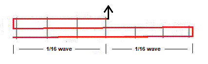
(a) The FCP covers a linear 66 feet (20m) for deployment. It does (x), (y) and (z). This solution does (z) by bending a single 5/16 wave wire into three folds, creating opposite phase fields from the folds designed to produce minimal net RF fields at ground.
(b) John Devoldere, ON4UN(SK), published 4 times 1/8 wave elevated radials. It does (x) and (y). This solution does (y) by cutting the traditional resonant 1/4 wave radial in half. This requires a 90 foot (27m) square for deployment.
Caution: In many cases the coil in John's solution is insufficient to reduce lossy feedline common mode current. The capacity from radials to ground varies by location soil characteristics with variable water content, radial height and radial length. Worse, the coil is frequently used to adjust SWR. Any of these defeat a one-size-fits-all coil to reduce lossy common mode current on the feedline shield. A designed-for-160m feedpoint common mode current block, or better, the brick wall current block of an isolation transformer at antenna feed point leaves the coil to adjust resonance/SWR without penalty. Exact 1/8 wave is not required, but in all cases radial lengths must be equal or adjusted for equal RF current.
(5) An FCP is not magic. An FCP has no gain. An FCP project improves an antenna system by replacing significant (sometimes excessive) ground and dielectric loss with a reliable small differential versus the same aerial wire over gold standard radials. Some have erected improved antennas because the short and linear footprint of the FCP allowed better placement of the aerial wire. Sometimes such multiple factor projects have produced startling performance improvements. But the best improvement comes when the FCP allows the first 160 meter antenna on the property.
(6) Inverted L or significantly slanted vertical aerial wires do not produce uniform RF ground fields at a given radius around the feed point as does a pure vertical. The aerial wire produces too-high fields underneath the horizontal or slant wire, and too-low in front. Thus significantly non-zero net fields exist nearly everywhere in the ground all around. Even gold standard radials have less advantage over an FCP with an L or slant vertical.