This article only lays out IsoT construction details unique to field adjustable IsoT's. The majority of material for constructing an adjustable IsoT duplicates a 1:1 bifilar IsoT. This common material is not repeated here and is presented in
After reading the following material for understanding and planning a field adjustable IsoT, to construct it begin at which links back to field adjustable IsoT material below as required.
Method B antenna matching is detailed in one of five methods for matching discussed. Method B is useful for matching almost any current fed 160m aerial wire over an FCP or other low R elevated counterpoise improved by or requiring an isolation transformer.
Detailed below, there are a pair of wide range, seven setting adjustable versions of the single core "4 inch heavy" IsoT. There are also a pair of three setting, more coarsely adjustable versions of the single core "3 inch regular" IsoT.
The values in the table are from the turns ratio squared formula. The 3 inch core 160m data is further adjusted for W2FMI's data, 50Ω to 44Ω as discussed later in this article.
Some number of variations in the winding itself can move a row's values all up or all down. Still, results achievable after best adjustment are likely within 49-51.5Ω, or probably 47-53Ω for 3 inch windings.§§
These adjustable IsoT's are constructed with fewer turns than a 1:1 winding on the aerial/FCP (A) side with the dropped turns added to the coax (O) winding. At the physical antenna feed location the installer can further adjust the turns ratio to transform a range of aerial/FCP RF resistance at X=0 (R0) values to 50Ω at the coax side of the IsoT.
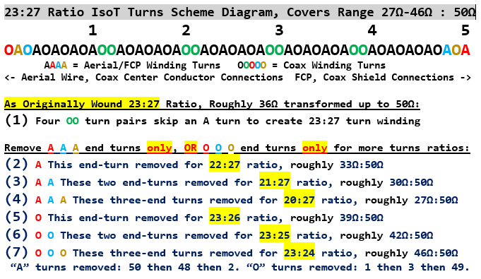
| 4 Inch Heavy, 23:27 | ---- | ---- | 27.4Ω | 30.2Ω | 33.2Ω | 36.3Ω | 39.1Ω | 42.3Ω | 45.9Ω | (160-40m) |
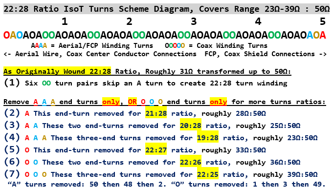
| 4 Inch Heavy, 22:28 | 23.0Ω | 25.5Ω | 28.1Ω | 30.9Ω | 33.2Ω | 35.8Ω | 38.7Ω | ---- | ---- | (160-40m) |
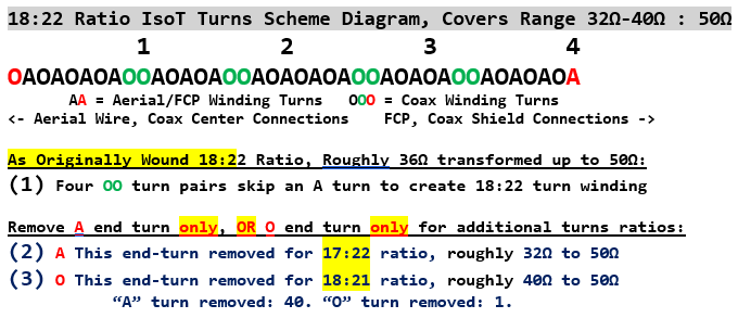
| 3 In. Regular, 18:22 | ---- | ---- | ---- | ---- | ~34Ω | ---- | ~38Ω | ~42Ω | §§ | (160m values) |
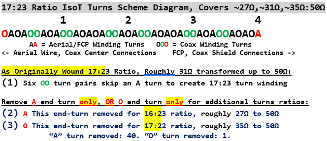
| 3 In. Regular, 17:23 | ---- | ---- | ~27Ω | ~31Ω | ---- | ~35Ω | ---- | ---- | §§ | (160m values) |
The transformers are constructed to allow removing a turn(s) on either the A or O winding wire (but not both on the same IsoT) for a given transformer's closest possible R match.
§§ These 3 inch core R values have been adjusted from formula (times 1.14) for windings' lower mutual inductance on 160, reflecting W2FMI measurements. While 3 inch transformers will work on 80/40m the 160m transform R values will not repeat on 80m or 40m, differing by the frequency variation seen in W2FMI's T300A-2 curve below. Experimentation will be needed.
The 3 inch windings can be a useful smaller device, with caveats. For Method T, transforming a 31Ω or 38Ω centered range up to a 50Ω centered range may simply be good enough for the installer. **
Likewise, for Method B, transforming a range centered on 27Ω, 31Ω, 34Ω, 35Ω, 38Ω or 42Ω to a range centered on 50Ω may be close enough or satisfactory given limited resources or situation.Perhaps the smaller core is all that is available or usable in the installer's particular circumstances. E.g. needing to reuse the enclosure, wire, core and hardware from a 3 inch 1:1 IsoT. The installer can use the 3 inch adjustable to allow at least some degree of adjustment, which might be close enough.
However, for more predictable and finer-grained transforms, robust construction and best performance with highly reactive antenna system loads, we strongly recommend the four inch T400A-2 core for a field adjustable IsoT.
** If you are doing Method T on an adjustable 3 inch core, use the 18:22 or 17:23 winding design as is and do not remove turns. This avoids core saturation loss that would not be seen on one of the 4 inch windings. See (5) below.
There are a number of factors making the T400A-2 core superior to the T300A-2 in an adjustable design:
(1) The T400A-2 core's inside diameter (2.25 inch vs. T300A-2 1.925 inch) allows more total turns on the core. This reduces ΔR per turn removed, ≈2.5Ω per turn in this application vs. T300A-2 4Ω or 5Ω per turn. A 2.5Ω ΔR allows output R inside 49-50-51.5Ω, regardless of luck on starting R.
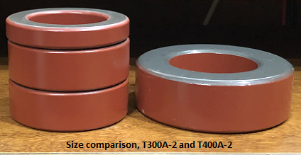
(2) The four inch T400A-2 has 2.6 times the core volume of the T300A-2 (185 cm³ vs. 71 cm³ per mfr. Amidon). Believe it or not, in photograph left, a stack of two T300A-2 plus a T300-2 has about the same total core volume as the single T400A-2. K2AV verifies that with the stack in one hand, the 4 inch in the other, they weigh about the same by feel, surprised as he was.
At this writing the Amidon retail price for a T400A-2 is 47.75 USD, the stack is 63.40 USD. If the total core volume is needed, which would you rather figure out how to wind and place in a project box? Do we need that much core volume?
Illustrated in the graph below from W2FMI's book,** a single T300A-2 core with only 38% of the T400A-2's powdered iron volume inside the winding reduces the coefficient of coupling on 160m and 80m, lowering output R. The triple stack of T200-2 has only 28% of the T400A-2 volume. At 1.8 MHz 50Ω input to a bifillar winding on a T400A-2 produces 50Ω output, a T300A-2 produces 44Ω, and a yet smaller triple T200-2 stack produces 40Ω, helping explain W2FMI's choice of the T400A-2 core.
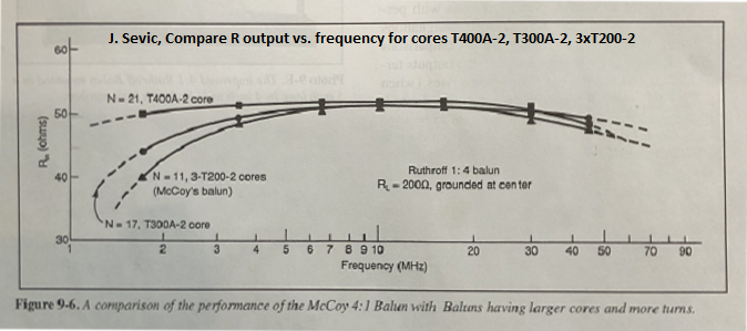
**Jerry Sevick, W2FMI(SK) "Understanding, Building, and Using Baluns and Ununs -- Theory and Practical Designs for the Experimenter", fig. 9-6, p. 60, © 2003 CQ Communications, Inc, Hicksville, NY
These variations persist whether the builder connects the windings as a balun or auto-transformer, or as a traditional transformer (e.g. IsoT).
(3) The value spread for the 3 inch adjustable IsoT will vary substantially with variance in the winding's tightness to core. Getting the winding flat to the flat side surfaces of the 3 inch core is much harder on the fingers.
(4)The crossover turn when a turn is skipped is harder to do on the 3 inch core. The flat side surfaces of the core are not large enough to easily support the crossover. The crossover has to be done on the outside circumference surface. This increases the fixed diameter of the completed winding by 7 mm (twice the wire+sleeve diameter), more if the winding is not nicely tight around the core. This likely would require redoing some enclosure particulars if reusing the components from an enclosed commercial 3 inch core 1:1 IsoT, including reusing its 4x4x2 inch plastic weather-tight electrical box.
(5) Due to the 3 inch core's drop off in the figure 9-6 curves above, skipped turns in a non-1:1 winding have to be managed carefully, evenly spaced around the core. Only one outside turn can be dropped from an end of the winding before flux "averaging" on the winding starts to fail. Failure of flux averaging produces spots where flux from the two windings does not sum to zero, leaving non-zero net flux to invoke core losses. For efficiency, this limits the number of usable Rin to Rout field-adjustable choices to three on a given 3 inch winding: Remove no turns, remove outside turn from clockwise end or outside turn from counterclockwise end.
Method B is set up to operate in proximity to the antenna system's managed resonance, with tuning by aerial lengths and owner-designed component combinations. Method T intends to avoid this work and deal with a cranky, non-50Ω antenna feed using a tuner. The chances of operating with much higher reactive RF current could be much greater, with a removed turn adding loss due to the smaller 3 inch toroid. Due to two and a half times the 3 inch toroid volume, the 4 inch will take over six times the power in the winding for the same amount of loss in the core.
Many hams spend their entire 160m operation on the low end of the band. An efficient wire antenna, 1.5:1 bandwidth only 25 kHz and 2:1 only 45 kHz, further broadened a bit by feed coax, life from 1.810 to 1.855 will not be an issue. But those who do CW contesting on 160 can go up as high as 1.865 or 1.870 during search and pounce or finding a run frequency in a busy band. Then there is the CQ 160 SSB contest which can fill the band at peak hours. K2AV's 1.8-2 MHz band coverage solutions are discussed below as idea fodder.
K2AV wound his first successful field adjustable IsoT on a single T400A-2 double thick #2 powdered iron core. Initially a 24:26 antenna to shack side turns ratio, he removed turns on the antenna side and rescanned the antenna system, one turn at a time, with a final 21:26 turns ratio.
The process uncovered impedance variations and some issues requiring solutions to finish. At K2AV, natural environment variation came from the weather, active and immediately recent precipitation, air absolute humidity outside of precipitation, the moisture content of earth underneath the L/FCP, whether sap was up and leaves on trees, or not.
Combined, over the entire year all the environmental influences can move F0 (the frequency where X=0) over a range approaching 14 kHz. At the same time R0 (the feed R at F0) varied over as much as 3Ω or 4Ω. Understanding variance from these was needed for satisfactory centering of an efficient 160 antenna's normally narrow SWR range. It is clear that as more loss was removed from the system, the natural variation emerged. At K2AV the IsoT was adjusted to dead-on match in the cold months for their bulk of high value operating. The more industrious could add a device to do a seasonal change of the turns ratio.
Issues uncovered included aerial wire inducing common mode RF current (CMC) on feed coax shield. This problem's solution required connecting the shack-to-antenna coax shield only to the shield of the coax jumper from antenna to analyzer while adjusting. Otherwise one would be tuning to a specific set of connections that no longer existed with the analyzer removed and all connections normal. We now include the modified jumper and checking for antenna induced CMC in the adjustment procedure so that the tuning to 50Ω persists after reconnecting the shack coax. Illustration, and details discussed in
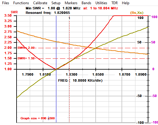
After available loss abatement (last of the loss list items) was applied, and two almost entangling trees taken down at K2AV, a 21:26 adjusted IsoT produced a winter season 51-53Ω R0 range in the shack, suggesting a direct aerial wire to FCP feed R of 30.8Ω, within an ohm or two of measured. An earlier 160m plot of K2AV's Trident L at that IsoT output is shown above.
The strategy in the K2AV shack uses his chosen "A-range" center of 1.82 MHz which covers nearly all CW operations well except for contest operations in the 1.850's, 60's and 70's. The matching is moved up 25 kHz to a "B-range" 1.845 MHz center by remotely switching in a series 3500ρF high current capacitor between the IsoT and the aerial wire.
The combination renders a winter-season combined 1.5:1 SWR bandwidth of 1.810 to 1.850 MHz, adequate for any amplifier. The 2:1 range, breakfast for the KPA1500's ATU is 1.800-1.865 MHz. Using the "B-range", the KPA1500's autotune or the 8410's SWR-insensitive 4CX1000A class AB1 tetrode finals further extend usable bandwidth up to 1.88 MHz. Both amps are OK up to 3:1 SWR and more at the antenna connection.
1.8-1.88 MHz easily covers all of K2AV's 160 operation except the once a year CQ160 SSB contest, when stations operate from 1.810 all the way up to 1.99 Mhz. The large bulk of the year's operation is "A-range", occasionally "B-range", less than 1.5:1 SWR, with the KPA1500 autotune in the shack largely selecting bypass. Above 1.88 MHz, using the B-range, switching the Ameritron ATR30 manual tuner out of bypass and tuning it by the numbers gets the rest. Effectively K2AV is using Method T for frequencies above 1.865 MHz in the CQ 160 SSB.
In practice the ATR30 tunes to the same inductance setting for the entire range, and only the two capacitor settings change, making for a quick and easy tune to tape diamond tuning marks on the capacitor's front panel.
At K2AV these harsh SWR's are handled by the voltage and current ratings of the "heavy" IsoT, plus unbroken LDF4-50 hardline all the way from the ATR30 to the IsoT, plus one 7/16 DIN connection on the ATR30 rear panel replacing a bakelite SO239. High SWR arcing was traced to that SO239. Now the setup handles 1.5 kW over the entire band without arcing or smoke. In contests though, power is reduced to 1 kW above 1.9 MHz.
A seasonal note: If you have a decently efficient L/FCP, depending on your latitude and climate you could have normal seasonal variations in the antenna system data seen in R+jX from an accurate RF analyzer. Depending on when the bulk of your 160m operating takes place you may have to pick a season to make measurements and do your field adjustments.
Seasonal variation seems very likely in temperate areas with a large population of deciduous trees. Trees that drop leaves in the fall, and have their sap recede in the winter will effect two distinctive periods of antenna measurements, more change if the antenna is on a lot where a "woodsy" look has been kept and nurtured. The periods are 1) leaves are still green, not started to turn and sap is still in the trees, 2) leaves and sap are down. This does not speak to all such variation across the globe, and everyone will need to gauge this issue, and account for it at their own location.
In areas without daily rainfall, situational variation occurs with precipitation, more marked with heavy precipitation.
At K2AV the spring and fall transition periods between summer and winter L/FCP data are only about two or three weeks. The rest of the time is clearly either the December through March, or May through October periods. This is seen clearly on K2AV's RBN numbers at W4KAZ, 7.2 miles away in Cary, NC. The reference measurements are always made around solar noon, when it has been dry for some days. Summer readings are mostly 55-58 dB, and winter readings are mostly 59-63 dB. It is not known just where the trees are that cause the loss, or the actual propagation mode.
Winter frequency where X = 0Ω (F0) is ~1.821 MHz in the dry, and summer F0 is ~1.812 MHz, going as low as 1.807 in heavy rain. Since I am peaking my system for the Fall/Winter contests, I do my adjustments December-March, not always the best for working outdoors.
The following discussion assumes you have picked any seasonal operating focus and are making measurements and field adjustments during that season.
There are some number of possible factors that could lean to one or the other of the windings. Some of these factors simply may not apply to your circumstances.
Either 4 inch transformer covers antenna R from 27Ω to 39Ω. If you think your R could get down to 25Ω or 23Ω, that leans toward choosing the 22:28. If you think your R could get up to 42Ω or 46Ω, that leans toward the 23:27.
If the antenna vicinity is mostly clear of dielectric mass, etc, except for the two support trees, that leans toward the 22:28. If there is large dielectric near or underneath, like a house, or the L's clearing is surrounded by close woods, that leans toward the 23:27.
If you don't see yourself in either extreme range, then pick the one which you think most likely to hit dead center without removing turns at all.
The 3 inch core probably is best used for Method T. The IsoT moderates the Z fed to the coax, and the tuner in the shack does the rest. This reduces the effect of large transformation steps, or one (only) 4-5 ohm jump up or down may be made by removing an end turn.
For winding non-1:1 field adjustable IsoT's, there are important departures from the 1:1 procedure. Read and understand all nine below before beginning winding.
1) The windings contain skipped (A) turns to create non-1:1 turns ratios. The skipped turns in the winding schemes are carefully spread around the entire core. If the skipped turns are all in one place, the opposing fields in the core will be far less balanced, creating a zone where the string of unopposed (O) turns will create a high net field with significant heat loss, especially so on the 3 inch core. Do not put all the skipped turns together to make the winding easier. This will cost you watts and could ruin a 3 inch core. Ask K2AV what super-heated T300A-2 cores smell like.
2) Match the left to right format of the winding diagrams by adding turns clockwise around the core as you wind. Leave 9" (230mm) wire free for attachments. Spare length on both ends is built into the table wire lengths for connections and to account for variations in tightness of the winding to the core.
Begin on the outside cylindrical surface, fastening the wire down with a tie wrap. Wind through the center against the inside cylindrical surface, back up and around to the next position clockwise on the outside cylindrical surface.
3) The winding wires are not the same length. The short wire is used for the Aerial/FCP or (A) winding and the long wire is used for the Coax or (O) winding.
4) The (A) and (O) wires are not taped together before winding and then wound simultaneously as if they were zip cord, as is often done for 1:1 IsoT's. The (A) wire must skip turns. Taping it to the (O) wire before winding will prevent skipped turns from being placed anywhere except at the end(s) of the winding.
5) The wires have to be wound separately. First, entirely wind the longer (O) wire. At the beginning firmly tie-wrap turn 1 to the core. Spread the (O) turns evenly around the ENTIRE core. Firmly tie-wrap the last turn to the core to secure tightness.
6) Flag the two ends of the (O) wire with electrical tape. On adjustable IsoT's, winding identification flags are only needed for the ends of the (O) wire. Interior turns were skipped while winding the transformer, and no adjustments are made to those, only to turns at the wire ends. The (O) wire ends are flagged. The (A) wire ends are not.
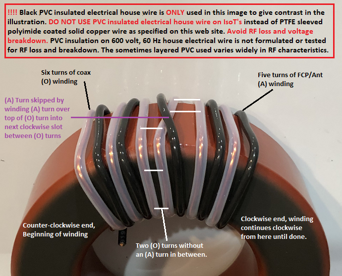
Some may have a source of red or other colored PTFE tubing. It is used in 3D printers, ordered by metric size specification. Use 2mm ID, 3mm OD to order, almost exactly #12 AWG standard wall. K2AV will be using red PTFE bought on eBay (search "red ptfe tubing") from China for (A) windings, and flags will not be needed. K2AV will replace the illustration above with his 23:27 ratio winding when he actually gets around to doing it.
7) Firmly tie-wrap the beginning of wire (A) to the core (turn 2 on the turns diagram). Wind the (A) wire, skipping turns as indicated by the winding diagram. Press the (A) wire firmly down between the (O) wire turns, tightly against the surface of the core.
8) The (A) wire will be laid across the top of an (O) turn to skip a turn. This is easiest done on the outside cylinder surface. On the 3 inch core, the outside cylinder surface is the only practical turn skipping surface.
9) While winding the (A) wire at a skipping point, squeeze together the two (O) wires without an (A) wire between them to recapture the space not used for an (A) wire turn. Then push the two (O) wires back counter-clockwise toward the starting end of the wind. As originally wound, both the IsoT's on a four inch core have 50 total turns, 40 on a three inch core. All winding space on the inside surface of the core is used.
The four winding diagrams are shown below. The diagrams are repeated in the printable instructions for use in adjusting at the antenna feedpoint. As has been the case at K2AV where PC's are not available at the best place for winding (family room rug), the printable instructions can be used for winding the IsoT. You can also select the diagram of interest with a mouse click and drag, and use your browser's printing facility to print the selection.
Return to in the main IsoT article.