This title listing will expand as Snips are added. Snip texts are all below, accessible directly from web page, email listserve or group listing links. This is done this way to preserve distributed links and simplify addition and maintenance of Snips.
Sneaky Destructive RDF Modifiers. Was: Beverage upgrade question. - Or, how dirt does its usual dirty thing to RDF. 20220825
Windstorm Variation of R/X/SWR Scans 160m L/FCP - Sustained March winds 28 MPH, gusts 45 at K2AV, 31 overlaid plots. 20220323 Additional graphics 20220331
===============================================================
===============================================================
(20220825) k2av.com/Snips.RDFKiller.html -- Sneaky Destructive RDF Modifiers. Was: Beverage upgrade question.
- Or, how dirt does its usual dirty thing to RDF. How to dumbfound and defeat the dirt.
This Snip is in response to a portion of the subject matter on a TopBand thread, posted quite a while ago. A timely answer was simply not possible at the time, given the detail and normally difficult, frustrating technical writing to properly treat this subject. Apologies for the delay.
On TopBand Reflector, Wed, Aug 24, 2022 at 11:13 AM David Olean Hello Kenny I have been playing around with antennas and feedlines over many years
and have found that your ears cannot immediately tell the difference
between a 1 dB change due to fading, atmospheric noise variations, QRN
etc. I have had scalar and vector analyzers over that time to determine
gain and loss improvements with some accuracy. A 1 dB change is very
hard to nail down with a quick A-B test. If you listen over a week or
so, you can tell that a 1 dB change in your system made a difference. If
you have a 2 dB change, it is immediately noticeable with A-B
comparisons. That does not mean that you should not worry about any
losses in your system. Get rid of any loss. They do add up. One thing I noticed was that hanging ferrites all over my beverage
feedlines was a huge help in keeping noise low in [my] system. You would
be surprised at how much noise comes in your receiver from the wrong
place! I put two ground rods at the transformer end of the beverage
separated by about 25 ft and outfitted with plastic boxes with toroids
and the feedline wrapped around it for each spot. I also put more
toroids and ground rods where the feed lines enter the building. There
are toroids all over the place and I live out in the country! See
ON4UN's Low Band DXing 5th edition. Joel is right in that you must
install the beverage properly. I am no expert on 160 meters, but Joel
sure is!! [Emphasis added.] Dave K1WHS
Remembering conversations at club meetings, over email, etc, we seem to spend much time on how to do wires for antennas, and then ignore one of the main culprits, literally underfoot. Dave's experience is in many ways parallel to mine.
What Dave did certainly works, it should have, but WHY should it work. Other methods and explanations are published, but how do they relate to one another. When does one method work, and the other not, and why? Otherwise is it just that one fella says A and another says B, and one is right and the other wrong? Then who is right and why?
Among us hams there exists an idealized, quite simplified "ground" concept, often heard at the radio club and seen on the reflectors: a great infinite charge particle sponge with infinite conductivity. We presume, that with a ground rod, we engage it with full unrestricted charge absorbtion and full unrestricted charge return.
The writer must admit here that the simplified concept does enormously simplify beer-muddled conversation over restaurant meals at radio club meetings. What ground actually does with a charge it receives from the other end of a ground rod is a mind-bending complex subject.
Most unfortunately, there is this actual, ugly, enormously variable thing called dirt in the complex, controversial, no-holds-barred, academic-grade version of the "ground" discussion. We get into details on dirt later below.
How can the dirt mess up our RDF? It can do that to us, without so much as a peep to warn us of its quietly deceptive process. First, lets clear up the RF gains involved.
Most of the discussed DIY RX antennas (ewe, flag, pennant, AY and such) are certainly directionally useful, can produce a significantly improved signal to noise ratio (S/N), if noise and desired signals are in different directions or polarizations. And (unfortunately) they are also lossy receiving. Lossy means that identical RF fields properly exciting both RX and TX antennas will produce lower feedpoint signal power on the receiving than on the transmitting.
The actual mechanism of the lower signal output on one is not specified and can be the result of various factors. This loss does not change the S/N performance of the antenna, as long as both desired signal and noise are being received entirely on the antenna per se, and the noise not being inserted somewhere else. A sufficiently quiet RX amplifier can bring the desired signal up to TX antenna level, where the S/N on the quiet antenna can clearly be heard. Both the ratio and the loss must be accounted for or the resulting numbers don't tell us what is really going on.
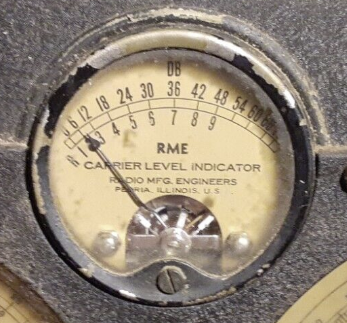
Image left is from a classic RME-69 receiver manufactured by Radio Mfg. Engineers, first introduced November 1, 1935. An interesting WWII story about one of them can be found here.
S9 is commonly defined as -73 dBm for HF. An S unit gain has been defined as 5 or 6 dB gain. 5 dB allows identical line scale ticks or 5 dB per LED both below and above S9. On the other hand, 6 dB is a comfortable doubling of voltage or quadrupling of power. 6 dB was clearly the concept in use with the 1935 RME-69 receiver's signal meter, with meter scale ticks numbered 1-9 below and 6 dB increments above the graticule. The writer has no dog in that fight, but will use 5 dB in the following because it makes the arithmetic easier to do in his head, and that's the scale on his K3 transceiver.
Let's say, while listening on an omnidirectional TX antenna, the desired signal was S2 and the noise was S3 in the K3's 250 Hz CW bandwidth. That would make the desired signal -108 dBm, and the noise -103 dBm. That's desired signal 5 dB down into the noise, S/N = -5 dB down, and the signal hard to copy.
Let's also say that the RDF of the RX antenna (from careful, professionally done, and accurate models) is 11 dB and it fully applies to this example's desired signal and normal direction of noise. All other issues being ideal, and the RX antenna having the same basic gain as the TX antenna in the desired direction, that should make the desired signal -108 dBm and the noise -114 dBm (TX antenna's -103 dBm minus the RX antenna's 11 dB RDF). The RX antenna audio's S/N is +6 dB, an S unit+ above the noise, probably quite decent copy if no QRM.
However, many RX antennas are lossy, and we need to examine what else can go on. Let's say that the RX antenna has 10 dB loss versus listening on the TX antenna. So the desired signal on the RX antenna is -118 dBm and the noise is -124 dBm. Not a problem so far because the RX preamp and AGC still produce the same RX audio's +6 dB S/N.
But we have made the assumption that in both cases, the entry mode of noise signal to the RX circuitry is by reception on the antenna elements per se, not by noise injection at some leaky point in the antenna/feedline system.
What happens to our RX antenna "reception" if the noise is entirely local, and the noise gained entry to antenna circuitry via common mode on coax shields, NOT via antenna wire pattern reception? Maybe the culprit is a bad compact flourescent in the house and has a nasty noise signal across all the 120 VAC wiring.
And let's start with an acknowledged assumption that common mode noise has equal entry loss to both desired pathways. Let's say that the common mode entry path has an entry loss of 10 dB. Starting with a -103 dBm noise signal inside the TX antenna circuitry, that means the noise was -93 dBm on the coax shield.
Now let us look at the RX antenna.
With an entry path loss of 10 dB, the noise level coming in from the common mode is -103 dBm. But we calculated above that the desired signal is -118 dBm in the RX antenna. Unfortunately, that common mode sourced noise is now 3 S units louder than the desired signal, rendering the RX antenna useless. This even though the RDF of the antenna proper is quite good and should have popped the signal right up. The poor common mode noise rejection has completely buried the expected performance and you are at the mercy of whatever EMI is going on in the house.
How good would the common mode entry path loss need to be, from RX coax to RX antenna, so that the common mode noise is 6 dB down from the properly received noise. That keeps the properly received noise the controlling noise, and allows us to hear the RX antenna's RDF perform its stuff.
Remember that the RX antenna's properly received noise is -124 dBm because the RX antenna has a loss of 10 dB. Then to not bother the performance, the common mode after leaking into the RX path has to be -130 dBm. We already determined that the common mode noise was -93 on the coax shields. Which means that common mode rejection has to be 37 dB!!
The measured common mode leakage path blocking of a commercial (Balun Designs) isolation transformer for an FCP counterpoise was 43.6 dB, only modestly clearing the required 37 dB in the example circumstances above.
As it turns out, in North Carolina's .002 S/m dirt, we are lucky to get 5 dB suppression from a ground rod, leaving us 32 dB or so to provide the isolation required by the example above.
From K9YC's 2018 Choke cookbook, 18 turns of RG400 wound on a single #31 2.4 in o.d. toroid will provide 10 kΩ series blocking. Discussed below, the common mode voltage has to divide between something like 165 Ω to the great signal sponge below the dirt and the 10 kΩ between it and the -10 dB common mode entry point. Using the -10 dB entry point into a 75 Ω circuit, that means a termination to the entry point of 37 Ω since that signal goes both to the shack and the antenna, or two 75 ohm loads in parallel. 10 kΩ, easily the controlling R in series with 37 Ω drops the common mode noise 48 dB in the RX antenna circuit. XXXXThe actual signal level of the noise is farther below the desired signal on the RX antenna than on the TX. So if the S/N is 3 dB on the TX, and 10 dB S/N on the RX antenna, there is still one element to work in, the difference in RX gain on both antennas.
Let's presume the RX antenna has 8 dB less raw signal gain than the TX. That means that compared to the TX antenna the raw noise level is 15 dB lower on the RX center conductor than on the TX. That means that common mode noise getting in somewhere can be 15 dB lower on the RX antenna shield than on the TX and cause the same interference to both receiving on TX and on RX antennas. It's entirely possible that common mode noise you can't even hear on the TX antenna can basically ruin any RDF advantage of the RX antenna, because common mode leaking into the RX feedline appears to be coming from all directions.
This is one of the advantages of the RX antenna system having a well-engineered amplifying device at the antenna, that's generally missing in DIY traditional RX antennas.
But beyond that, it is clear that unamplified RX antennas need a lot more protection from common mode noise.
It's at this point I start hearing suggestions that grounding the coax shields at the dwelling entrance will remove common mode. Without careful attention to a small stack of caveats, that recommendation can be anywhere from not-as-true-as-we-would-like to not-true-on-this-antenna/coax-at-all.
The dwelling entrance grounding we are talking about is what we all should be doing to protect from induced lightning and satisfy electrical codes. Totally necessary, effective for their purposes, and heartily advised, but that ground at RF is really not like the mental image so many of us have of grounding at RF.
We think of ground as being this infinite charge particle sponge. Put a pile of electrons on a ground rod and the ground will instantaneously slurp it all up and then have it ready for full instantaneous return barf when the charge on the ground rod reverses and wants all its charge particles back. Then it gladly instantaneously supplies an equal barf of electrons as the waveform goes into full reverse polarity.
That's what we want, what we're hoping, anyway. Were that truly the case, then grounding the coax shield gets rid of all common mode. Wipes it out. We wish.
I wish more than anybody. But I live in North Carolina, mostly gifted with .002 Siemens/meter dirt. Without getting into the brain-dissolving math, I'll just say that at 160 meter RF, we get the equivalent of a 25-100 ohm series resistor between the end of the ground rod and that infinite charge particle sponge we call earth. We have actually measured that, but that's another story.
So now what we have is a series resistor between the coax shield and "earth" (the infinite charge particle sponge).
And if we have more than one "grounded" conductor (like our entire house electrical system) at the entrance, coaxial shields conductors and house ground/neutral conductors will be zero ohms connected to each other, and all of them sharing that resistor to the great sponge.
Here Ohm's law becomes our enemy. Any noise voltage on any house wiring safety grounds or neutrals will have an IR drop across that resistor of all the nasty common mode noise in the house. And if we have grounded all those incoming coax shields at the same point?
When we grounded those conductors, we gathered up a fixed percentage of all the actual house conductors' noise voltage in a basket, and dumped it on all the incoming coax shields as common mode noise. The true RF impedance to ultimate ground in parallel with whatever miscellaneous impedance at RF presented by the coaxial shields.
Oh, I can fix that. Don't ground the coax shields at the dwelling entrance!!!
Naughty, naughty, naughty, naughty ... remember lightning and the electrical code. You MUST ground them there. You are stuck with that. The point here is to see and understand that mandatory electrical service grounding for what it actually is and does, and what it does not, AT RF frequencies.
How about a good stiff common mode choke, between the shield grounding and the coax to the antenna? OK. That blocked the house common mode noise from getting on the RX coax with a free ride back to the RX antenna.
But that coax shield laying there between house and RX antenna will forever be a common mode antenna, picking up stuff from directions you don't want to listen to. That includes picking up noise from the dwelling getting there via radiation. So you also have to block the common mode at the RX antenna. Some RX antenna devices have that built in, often in the form of a small isolation transformer. If you are doing an RX antenna yourself, you have to provide that small isolation transformer yourself. Make sure there is no DC path of any kind between the coax shield and the RX antenna.
So you have a choke on RX coax just before it is grounded at dwelling entrance and an isolation transformer in the circuitry at the RX antenna feed. Good, but you still might not be done.
If the length of coax shield is near an electrical half wave, you have the problem of common mode standing waves on the shield. This means there is (relatively) high current in the middle of the length, and high voltages at the ends of the length. Ferrite common mode blocks work best at points where there would otherwise be high common mode current. Ferrite blocks are far less effective at high voltage points. This includes isolation transformers as blocks. The high voltage pushes more signal through the imposed R of the ferrite and across the blocking C between windings of the isolation transformer.
The only defeat for this half wave that is not loaded with confusing caveats is to add another common mode block near the center to break it up into two quarter waves which will be anti-resonant.
If there is sufficient distance to the RX antenna, a grounding points (except at dwelling entrance) can be replaced by coiling the feed coax however many turns can be placed into a pair of large #31 ferrite snap-ons, repeated at quarterwave intervals. This method has the distinct advantage of not breaking a feedline or opening the jacket to produce the ground connection. Personally, particularly with North Carolina .002 S/m dirt I think a series 14K block following a quarterwave will do more than a 100 ohm shunt to ground following a half wave, especially if there is any chance of some local dirt aspect that will cause the feedline shunt and a necessary RX antenna ground to share a resistive path to the infinite charge particle sponge below.
If you are just doing A/B testing, you will see corrupted results with no indication that the result was corrupted. No signal to noise improvement here, RDF must be awful. Model looks good, but I must have done something wrong with the wires. Maybe a pennant doesn't work next to a building. Eh, tear it down. Put up that neat new XYZ RX antenna in QSY magazine. New wires, different design, but same coax and common mode situation. Sigh.
Of interest, with no improvement in the common mode stuff, the RX antenna with most gain hears better, because the RX antenna isn't providing the controlling noise, the common mode is. RX antenna with better gain hears better. Here warning bells should be going off. RX antenna with best signal-to-noise design should be hearing better.
Getting suspicious yet? But this stuff
Not only does this apply to listening on RX antennas, but to listening on the TX antenna as well. This is important because the number of 160m ops only able to listen on their TX antenna probably grossly outnumbers the number of ops with listening antennas. I frequently listen diversity between 160 TX antenna and my 40m inv V.
On 160, my 40m V gets better signal to noise on 160 than most wires I have set up for a RX antenna. Importantly, the balun on the V has quite respectable measured blocking on 160, keeps the 160 common mode out of the presented signal, and the K3 preamp brings it up nicely. Diversity really helps my brain pulling signals out of the noise. But the TX (Inv L over FCP) had some RX noise issues, and turns out it was hearing the noise in the house more than it should have been.
The problem was on the coax feed to my L over FCP TX antenna. That string was Inv L over FCP to isolation transformer, then coax to dwelling entry point, where shield of the hard line is grounded, as are all the TX, RX coax entering there. This is for lightning and satisfying the electrical code. Have to do it.
This winds up making the coax shield back to the L/FCP a miscellaneous wire, essentially open at one end (isolation transformer) and grounded at the other, sharing an RF resistive ground with noise current from the house into ground. This is fine for lightning protection and electrical code, but has a down side for RF. The ground is actually resistive, a conductivity of only .002 S/m in this part of the country. This puts RF noise current on all the grounded conductors at the entry point, including onto the shield of coax to the L/FCP.
That's not an efficient TX circuit, but but it IS a wire connected to ground at one end and open at the other. That makes it a de facto, unwanted RX antenna listening to all the RF noise in the dwelling.
The coax shield end at the isolation transformer between it and L/FCP becomes the voltage end of the wire. The grounded end of the coax shield becomes the current end of the wire. It's high voltage vs high isolation Z at the isolation transformer end, therefore not as effective a block as low voltage vs high isolation Z. Not as effective against whatever noise from the house is induced on the coax shield.
The current at the grounded end is what produces the voltage at the isolation transformer end.
We have to keep the grounded coax shield for lightning and electrical code. So one makes a common mode choke with RG400 and #31 material FT240 cores from K9YC's excellent cookbook and inserts it between the dwelling entry ground and the coax to the antenna side.
Now current is blocked at both ends of the coax from dwelling entry ground to TX antenna. Choke on one end, isolation transformer at the other. A surprising amount of noise disappears from the TX antenna.
The Inv V has 245 feet of buried coax out to the tower end of my skinny lot, which acts as a common mode choke.
There is an easy subsidiary lesson here about keeping shields common mode clean up at RX antenna feed points. Transformer feed at the RX antenna, no connection of any kind from primary to secondary, inductive pass through only (RX level isolation transformer), feed coax NOT grounded at the RX antenna. Common mode choke on the RX antenna feedline 1/4 wave from RX antenna. Feedline grounded on shack side of common mode choke.
Some will say just to ground it, choke not needed. But if your ground is poor for this purpose, as in North Carolina .002 S/m conductivity (think 500 ohms resistance), your grounding works fine for lightning with code spec grounds but still leaves a common mode RF voltage at the ground point. This is almost guaranteed to be worse around houses, where heaven knows what is in the "ground" prepared for foundations and yards, etc.
The problem is that this common mode noise voltage getting into the RX system is constant, and does not vary when switching RX directions. Hmmm... Must it be that the RX antenna RDF stinks? Until you have scrubbed the feedline shields of common mode, you will never know. Have to get to the point where the only time you hear the house noise is when you are pointing the RX antenna at the house. Then you can compare RDF just due to the antenna.
===============================================================
20220323 Windstorm Variation of R/X/SWR Scans 160m L/FCP
- Sustained March winds 28 MPH, gusts 45 at K2AV, 31 overlaid plots. Additional graphics 20220331.
Would you have guessed that there is a way for the wind to wobble an antenna wire, so that the feed X would wobble, the feed SWR wobble worse, and the feed R would not? Read on...
Unremarkable conditions for a March 7 in eastern North Carolina, high winds were blowing the trees around at K2AV, gusts up to 45 MPH (20 m/s). The 160m L over FCP was whipping up, down and around quite a bit. It was a sunny partly cloudy day with firm dry ground underneath. Not yet trees with full sap and leaves, but buds on maples were just showing.
Out of curiosity, K2AV turned on the AIM4170 RF analyst, and switched the L over to the analyst to have a look at the R/X/SWR graph in the wind.
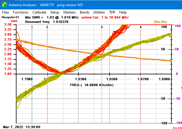
To illustrate the wind variation with the 4170's control program, one can slow the scan by making the frequency step very small and setting the 4170 for continual rescan with overlay. If there's no wind, the rescan simply repeats the prior and it still looks like one R curve, one X curve, one SWR curve. If the data is varying, the lines get wide. The March 7 scan results, 31 overlaid scans covering 10 minutes, are shown above.
Green trace is X, brown is R and red is SWR. 1.8 MHz is dashed vertical line with blue in it, 10 kHz per vertical division. As expected, the X and SWR curves were wobbling quite a bit. But the R seemed steady, odd given the variation in X and SWR. A 1.820 MHz resonance was the deliberate 2021-22 winter setting. The banner resonance figure is from the 31st scan.
The AIM4170's PC control/display program has an excellent calibration-driven subroutine to convert the shack readings to what would be seen at the isolation transformer coax connection. If the particular calibration for the particular feed coax is current, the shack AIM4170 and the Rig Expert AA-55 at the feedpoint deliver the same curves. So you are viewing the R,X,SWR at the antenna feed.
The results, X varying 10 ohms or more at a given frequency, frequency of X=0 varying down 5 kHz, SWR varying 45 points, more out of band (2.25 to 3.20 at 1.792), but R varying not even 2 ohms at 1.820, is an interesting conundrum. When sap and leaves are all in, the steady daytime, dry ground R will seasonally go up 3, maybe 4 ohms. But no wind effect on the R.
In the X and SWR curves, you will see some number of single trace large excursions. These are present on both X and SWR, directly above each other. There are no such excursions on the R curves. Go figure. Conclusions and explanations posted here if any emerge.
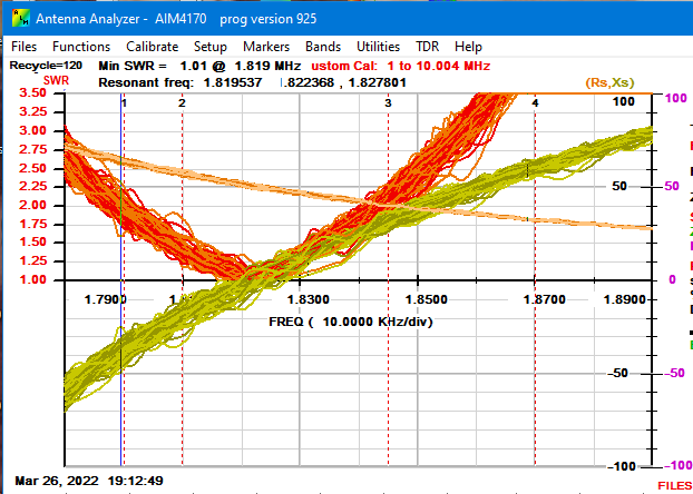
20220331: Additional graphics: Similar conditions and same procedure as above, ran 120 overlaid graphing cycles over 40 minutes, identifying larger variations: R variation of 3Ω, maybe 4Ω, X variation of 25Ω or more, and over 100 point variation in SWR. Banner line "Resonant freq:" numbers indicate that during cycle number 120, X crossed the zero axis three times. This additional graphic gives a documentary explanation for fairly rare odd SWR faults on the KPA1500 previously assumed to be wind-driven shorts at points never identified. A further incentive to reinstall shock moderation. Not a difficult job, just the time to do it.
K2AV Gut Speculation:
The R value is most determined by portions of wire carrying the most RF current. Final radiation resistance has to do with wire length, shape and freqency, plus a miscellaneous R from inducing ground loss. A smaller added R comes from invoking various dielectric losses. The highest RF current summations are from the FCP and the vertical wire.
The FCP itself doesn't blow around in the wind and generates very little R in the system due to its folds design, the point of having an FCP. That leaves the vertical wire as a potential wind-variance culprit, but by observation the vertical wire is far steadier in the wind compared to the horizontal wire.
A varying X value is most determined by capacitance of wire "to the rest of the world". The greatest current from this ad-hoc capacitor will occur where the voltage is the highest, or out at the far end of the horizontal wire. The far end is out at the end-supporting tree and moving a lot. Variation in that capacity changes the effective electrical length of the horizontal wire, hence varies the X=0 frequency.
Using a weight through pulleys to moderate wind pulls on the horizontal wire, the wire would move up and down far less. Probably the wind variation in the graphs would be far less. But K2AV's shock moderation wasn't put back up after the L/FCP was moved up by the house to get away from the new 13 kV primary lines out on the service road. Graphs above would seem a good reason to get that done this summer.
Better ideas? Email peerreview[at]k2av[dot]com.